
I started with some white "paper" (actually cloth and plastic) lanterns from the $2 shop. As supplied, they were simply a string of white lanterns with (disappointingly dim) white LEDs inside. But they were cheap, and I wasn't intending to use them with those LEDs anyway.
I set about replacing the white LEDs with RGB LEDs. I had also stripped down an old (pre-USB) 25-wire printer cable from my junk collection to get some appropriately coloured lengths of multi-strand* wire. I was able to extract 2x 3m lenghts of cable each in the colours Red, Green, Blue and Black, which will make the wiring a lot less difficult on my brain than having either no colours or colours with no relationship to the LED colours they drive. The black cable is the common voltage return, of course.
* Multi-strand wire is more flexible than single-strand and less prone to stress-breakage when repeatedly flexed. It also hangs more naturally. Multi-strand network cabling would work fine too, though you would have to use the orange cable for the red chanel and brown (or one of the whites) for common return. Of course single-strand wire will work fine electrically, it will just have angular kinks and less natural flexibility.
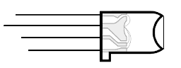
One other thing about LEDs: they are fairly directional. I used a Dremel™ and a ball engraver bit (and a steady hand) to turn the convex lense into a concave bowl. This will give the LEDs a much better "side-lighting" ability rather than sending a 15-30° beam mostly out the front (which would not light the lanterns so well). Another trick (not suitable for this particular application) is to make a hole in a white ping-pong ball and push the LED in as far as the rim.
Starting with just 4 LEDs, I wired them in parallel along the wire. I considered putting load resistors on each active pin, but decided it was too much trouble. As it was, the bundle of cables coming in and out of each LED was fat enough to barely fit in the heatshrink tubing I had.

I stuffed some slips of scrap plastic between each leg, so that they wouldn't short when scrunched together, then slipped some heat-shrink tube over the lot. Heat-shrink tube, as the name suggests, shrinks when you heat it. Holding it over the soldering iron and turning it like a spit-roast shrunk the tube over the LED, plastic strips, solder and bare wire, making it all relatively neat. The LED assembly is slotted back in the lantern frame.

With just 4 LEDs, we are (barely) within what the Arduino can power off a single pin*. I plugged the R,G,B channels into PWM chanels 2,3,4 respectively of an Arduino Mega** and the black return line into a GND pin. Onto the Arduino, I loaded the AnalogWriteMega demo code, changing the const int lowestPin = 2; value to 10 and const int highestPin = 13; value to 12 (since I am only using channels 10,11,12). The lanterns pulsed R-G-B-R-G-B-R-G-B-R-G-B and so on. SUCCESS!

* Arduino output pins can drive a maximum of 40mA, LEDs typically draw 20mA. We can only get away with the total 80mA here because a) we are pulsing the LEDs rather than running them continuously (giving the overloaded transistors time to cool before they fry) and b) this is just a quick test setup and wasn't left running for any length of time. Actually, there is a good chance the Arduino is under-powering the LEDs rather than overloading itself, making them dimer than they will be when we implement a proper transistor switch that can deliver long-term power for a whole string of dozens of LEDs.
** The MEGA is what we have in our student labs. With some minor alteration to the code any Arduino with 3 chanels of PWM or more (such as the cheaper Uno, or similar older models) would do fine.

As you might have noticed, this is the same power-switching circuit as from the Orac project. We are switching 16 LEDs at 20mA each, making 320mA per channel, well under the 4A capacity of the TIP122 transistor. The 470Ω R1 limits the current to the base (switching) pin to just enough to fully switch it. R2 limits the current going to the LED string to around 320mA@5V. I have put R2 on the line with the LEDs rather than with the rest of the circuit because if some time I make a string with some different number of LEDs, the resistors will have to be different to suit the needed current.
You will also see I have purchased an Uno board in place of the borrowed Mega from the labs. I really have no use for all those extra digital I/O lines on the Mega in this project, and trying a variety of boards is important for my job if I am to provide good advice to students.
This circuit is triplicated, once for each colour channel Red, Green, Blue. Actually, Since the Arduino I am using (Uno) has 6 PCM outputs I am going to double it again to support two strings of 16 LEDs each, separately controllable. Blink blink blink blink blink blink blink blink blinnnnnnnnk - Dueling LED strings!
I am using a short strip of aluminium angle as both a heat-sink for the transistors and as a mounting bracket for the sockets the LED strings plug into. Because of the latter, I don't want to have stray voltage in it, so the transistors are this time electrically-insulated from the heat-sink with a strip of non-electrically-conductive heat-transfer material (yellow) and ceramic isolating washers (under the screws). The heat-transfer material and the ceramic washers were salvaged from under transistors in old TVs and computer power-supplies, but are cheap to buy too.
I used some brass spacers from an old computer case to mount the Uno on the block of acrylic too (I need three more red washers from home before I tighten those screws that are missing them above the board). I then connected the (colour coded) wires to the PCM outputs. I dabbed a layer of solder over the ends of the wires to make them a bit thicker so they would hold more firmly in the sockets. Also some rubber feet that I had stripped off an old computer keyboard before throwing it out (yes, I keep all sorts of things like that!) were plastic-super-glued to the four corners of the base of the acrylic block (two are under the aluminium, so can't be seen in the image above). Finally, I soldered the limiting resistors on to the appropriate transistor legs. Blu-tack made a good solution to holding them in place for the soldering process:

I now have one of the two strings of lights wired (what a tedious job - I ended up doing four LEDs a day because I didn't have the patience to do more in one sitting!) and now I need to write some simple random-colour-change code. Stay tuned.
Start of teaching session has me a bit busy (mainly sourcing parts for and trying to fix 16mm film projectors without any instructions at present). It is a hassle to get the Arduino™ software installed on my centrally-managed office PC, and I can't disappear to the labs for any length of time just now. I do have the latest Arduino™ tools on my Linux box at home, so might do some work on my own time some weekend coming up. Few other at-home tasks out-priority it still there too, though.
My final intention is to try out (and document) a variety of sensors to make the light string(s) react to changes in the environment around them.
Same circuit, different application (created for use by Kraig Grady in performance work):

This time, 5 ultra-bright LEDs* are driven independently. Also added a potentiometer for speed control.
* This type of 12Volt LED has a driver circuit built into the base, which I removed as it didn't like arduino PCM.
 Glenn's home page.