 Glenn's home page.

Designing and 3D printing some custom insets for off-the-shelf plastic storage cases. Mainly for my custom gaming dice which are themselves primarily 3D-print demos for students where I work.
3D printing, particularly with consumer-grade printers, has a lot of shortfalls, so when you can print smaller/simpler/fewer parts to modify a mass-produced item to your needs, you will often get a better end result than a full custom-print could provide.
I had some cool-looking plastic cases I found randomly and bought cheap online. I later found out they are offically "Fishing tackle cases" but I have been finding all sorts of uses for them from travel-toiletry box to sewing-machine-parts storage. When I designed and made some custom 3D-printed dice for a class demo, I wanted a portable case to cart them about in, and again this case was just right.

These cases come with little flip-lidded compartments built-in, which wasn't suitable for my intended use. I found that they are glued in, and by soaking the case in near-boiling water for a few minutes the glue softened up nicely and I was able to carefully prise out the insets with the same paint spatula that I use to lift 3D-prints off the printer bed when they are done. I was able to use these insets, along with direct measurements of the insides of the outer cases, to design some new inset blocks in the Blender open-source 3D modelling environment.
I printed these on our crappy-old filament printer, mainly because it uses a different (and annoyingly fragile) 1.75mm gauge of filament while our newer higher-quality printer uses much more robust 2.35mm gauge, and so I am trying to use the old stuff up prior to junking said crappy-old printer (or at least relegating it to an emergency fail-over kept in a deep dark cupboard). It took several attempts to get something useable out of the thing - I was using ABS filament (again to use up the horrid stuff) which didn't help, and because these prints feature long strait edges, plastic shrinkage was proving to be a real pain, with corners lifting off the print bed during printing. On the up-side, with each failed iteration, I was able to fine-tune my dimensions for even better fit, reducing a 0.5mm gap, to 0.1mm tight fit on every dimension.
Our newer, more expensive, filament printer actually produces rather decent results, but the old-clunker is noticably lower resolution, but fine for this type of print-job where the layering doesn't really detract from the look (or function) of the final part.
So, in the end, I used up a lot of junky old filament, and have a nice dice case.

Here is the Blender file for the insets (easy to remove the D8 slots and put in your own for whatever you like).
Note:The label on the front (top image) was done in an office label-writer and carefully trimmed to fit an existing cavity on the top of the case.
Having made the above dice box, I decided to re-use my carefully-fitted insets to create inserts for another such case to hold the small paint pots used for model painting (mostly just painting the dots on my dice, if I am honest). Also it became an experiment with embedding magnets in the 3D print.
The paint pots being held are 14ml Humbrol enamel paints, intended for painting small things like models.
While I often try to print these insets in ABS (mainly because I acquired a huge number of old rolls of the stuff second-hand), I am using PLA this time as it is a bit more resistant to the kind of paint-thinner-like chemicals it is going to be around in this usage. PLA is also a good bit easier to print with, and is also plant-oil-based rather than petrolium-based as most other plastics are, so carbon-sequestration too (as long as it doesn't end up in the sea as micro-plastic particles!)

Starting with the same type of plastic box as I used for the above custom dice case, I re-used the basic 3D model of the top and bottom inserts I had developed for that. I again removed the supplied insets by placing it in near-boiling water for a few minutes to soften the glue, then carefully pry out the insets with a spatula.

I had space for 10 paint pots, and a bit of extra space that (almost - I had to trim the handles down 20mm) fit two of the tiny brushes I use, so I made slots for those too, rather than completely waste the space.
The Bottom tray is to hold the paint pots in place, and - when closed - the top section clamps down on them just firmly enough to (hopefully) stop any transport-accidents with not-quite-on lids.

I also had about 8mm of spare space in the lid of the box. I had hoped to put extra brush-storage in here, but it wasn't quite deep enough. Still not wanting to waste the space, I instead made a rectangular recess to hold a laminated safety-data-sheet (SDS) for the paints.

To achieve this, I split the top insert into two parts, a thin one that would be glued into the top of the box lid, and a thicker part that will be removable.
Rather than have the removable insert falling out of the lid every time I opened the the box, I embedded strong magnets in both top and botom pieces. I left cavities the size of the magnets in the 3D prints and paused the print at the top of these cavities, super-gluing in the magnets before resuming the print. Super-glue was necessary to hold the magnets in place, otherwise they would jump off the print and stick to the print-head rails as they got close! I printed two layers - about 0.6mm - over the tops of the magnets to make it look nice and neat. I smeared and finger-tacked some superglue across the tops of the magnets too, prior to restarting the print, so the layers printed over them would have a rough surface to better stick to.
So now the removable panel stays in the lid, but is easy enough to pull out if one wants to get to the SDS.
You can download the Blender 3 and STL files I used here.
These files are provided as-is and without warranty or any restrictions on usage or distribution. You will probably need the blender file to generate new STL files, since you will need to resize the magnet cavities to match whatever magnets you have - leave an extra 0.5mm space on sides (not top and bottom) to account for side-expansion in the 3D print process.
The manufacturer's 3D slicing software is no longer optimised for my old printer (I have a MkI and the software is presumably optimised for the current Mk3 model these days). I had to slow it down to half-speed, from the driver defaults, to stop the stepper motors over-running themselves and printing at a slant.
There is also a bug (probably only with the manufacturer's slicing software's interaction with my MkI) that was causing layer drift on the 'top' layers of the print (6 layers, 2mm, thick in this case as I wanted a bit more strength on these faces of the inserts). This was an issue even at half-speed printing. Backing off to quarter speed for these specific layers fixed this. Over subsequent prints, I gradually bumped back up to one-third speed without issue and decided that was good enough!
The long strait sides of the print are a bit finicky and have a bad habit of corner-lifting off the print bed during early stages of printing, ruining the later layers. Online suggests a 'thin smear' of glue stick. I found that a 'thin smear' was not enough, but layering it on thick as lip-gloss worked effectively for providing good bed-adhesion. Long strait edges are apparently a bit of an issue for this type of 3D-print technology, as I didn't have any trouble of this nature with some similarly-sized organically-shaped PLA prints I did for a student just prior.
Initially, I slightly under-sized the magnet cavities with the intention of using a soldering iron to heat the magnets and press them into the holes. Heating the magnets above the softening temperature of the plastic de-magnetised them (not a huge surprise - heating iron de-magnitises it, so the same obviously applies to neodymium magnets - I just wasn't sure at what temperature the effect would kick in). I re-sized the cavities and super-glued the magnets in instead. Neither the lower levels of heat coming up from the heated print bed (through several layers of printed plastic, too), or the spot-heat around the in-print plastic as it comes from the print nozzle, seem to have been high enough to damage the magnets, in the latter case, the heat probably soaks into the metal of the magnet, and 'averages down' quickly enough to avoid any such issues except, possibly, on the top fraction-of-a-milimeter of the magnet, if even that.
The magnets are still visible through the 0.6mm (2 layers) of plastic covering them. Burying them deeper would have reduced their magnetic attraction (further appart) and as these magnets are normally concealed, I don't really care. Using a darker plastic colour would likely have also concealed them better (if that actually mattered to me in this instance). I specifically did these inserts in white to contrast with the paint pot colours.
The two-layer over-print on the magnets does, however, ensure the surfaces are properly smooth (and easy to lightly sandpaper even smoother), which having the magnets flush with the surface would have made more difficult. Plus I would have had to use removable supports, and the extra clean-up that entails, in one of the trays if I had done it this way.
If I wasn't doing this as a learning exercise (and manually embedding magnets mid-print, in this case), it would likely have been cheaper, probably have been quicker, and definately have been less frustrating to send my 3D files off to a commercial 3D printer. Though through the multiple (twelve!) day-long print failures I had to go through to get satisfatory prints, I did also have the opportunity to make unrelated small adjustments to the model that became apparent from examining the mis-print parts: just minor tweaks, and nothing I couldn't have lived without, but small improvements nonetheless. So for iterative prototyping, obviously a cheap 3D printer can still be a very useful tool.
Okay! Well, I have generated so many variations of my demo-dice now that my nice 3x3-pair storage case is no longer enough! Never-fear. I had a small crate of Tactix™ storage boxes that we used to store some student-loan audio recorders in. The recorders are now in different cases, but I kept the Tactix™ cases - they are good cases, though we found the acrylic latches were a bit too fragile for normal student handling, hence moving the audio recorders to something more student-resistant.
Hmmmm.... I wonder if I could 3D-print some more hardy latch-parts - it would have to be a resin-print: a filament print would de-laminate and unravel pretty-much instatly under that sort of force! Those latches might barely fit in our tiny resin unit....

A bit of careful measurement and one test-print later, I had a nice insert design for these cases.

I generated an insert to go in the case's base, which provides a partitioned general storage space as well as a rim to rest the dice-display tray on. First one was in ABS plastic (shudder) which, as expected, came out badly. But I finally used the last of the damned stuff up, and again was still able to use the bad print for micro-adjustments of my measurements to a tighter fit. Then on to old PLA plastic, the first reel of which went strait in the bin. Then on to PLA plastic which hadn't been stored open in a mouldy back-office for who-knows-how-many-years-before-it-came-to-me, and the prints suddenly went much more smoothly (store your filament in zip-lock bags with moisture-absorbing-gel-packs, kids!)

And another insert with a different compartment configuration. .... Dang! My D60 is a little too big for the compartment height. I checked my model and even if I make the bottom of the upper tray as thin as structurally possible, don't have quite enough clearance to accomodate it. Oh well.... I probabiy should make a separate display case for those dice anyway. I also cut out a piece of adhesive-backed felt for the bottom of the case, so loose dice don't rattle as much in my bag.

On top of the divider-insert sits a tray with space for 4x4-pairs of demo-dice (currently packed 3x4 but I can re-arrange as needed, of course).

And since this case has a transparent lid, the dice are still on display even with the lid closed. The tray is at the right height that the dice fit snugly under the lid without rattling about when it is closed (except the pair I carved from D-8 blanks bought online, as those aren't confomant to my 21mm bounding box for my 3D-printed ones, but those are still secure-enough).
I also used a dremil-bit in a drill press to grind flat the Tactix™ logo - nothing against Tactix™ or their logo, but that little slot is perfect for my own office label-writer sticker.

Here is an alternative top-tray. This time I have cycindrical slots for eight game-pieces and dice-pair slots for each (so each player can have their own themed dice to match their game piece).
Here is the Blender file for the various inserts and trays above (easy to remove the D8 slots and put in your own for whatever you like, or modify to your needs in any other way desired).
Back to fishing-tackle cases. This time some smaller ones:

As above, I gutted the case, then measured and generated inserts for them.

For these inserts, I made a case to hold two 8-sided-dice pairs and three cylinders for holding game miniatures.
One minor change I have made to this case (which I will likely carry through to other similar cases if I do any more) is to drop the deeper cavity 5.2mm, leaving a bit of space and letting the centers of the dice, etc. sit silghtly raised above the surface of the insert. This saves a bit of print-time and plastic, though my reason for doing so was more for aesthetics and handling.

My idea for game miniatures is to have 64:1-scale figures 3D printed and embed them in 21mm diameter by 42mm high cylinders of art-epoxy (formulated for high transparency without the yellow tinge of regular epoxy resin). Those would then go in the cylindrical slots.
I have a machinist doing a pair of stainless steel cylindrical moulds for me now as a low-priority job. I could either print the 64:1 figure myself and hand-paint it, or get one full-colour 3D-printed by an online company (One of my favorite local printers, Zeal-3D, seems to have a side-line in this now!).
One thing left: I deliberately over-sized the cavities by 1mm, so I could laser-cut some adhesive-backed-felt linings for them:
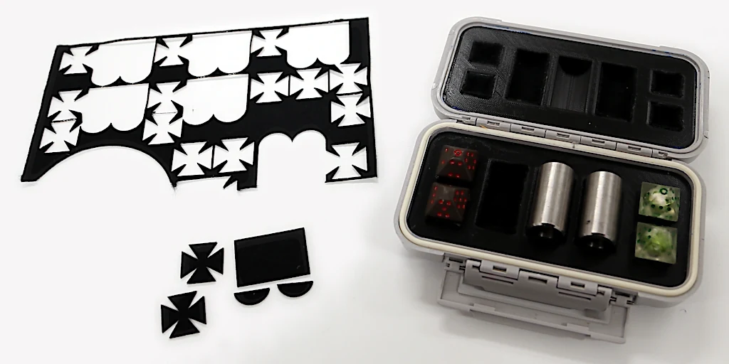
The stainless-steel cylinders are just random place-holders for what is actually meant to go in those slots (epoxy-resin-encased game figures). Because I tend to design everything in Octal Planck Units, some parts from an unrelated project happened to be a perfect fit-substitute.
Here is the blender file for the small-case trays. Probably not much point posting STLs as it is the inserts themselves, rather than the my-use-specific dice/cylinder cut-outs that would be of interest/use to others.